

The “Wave” class of 21 ships (20 to be RFA’s) were built to a standard 1943 wartime design with slight variations in layout and complied with the builder’s normal construction plans and details. The designs changed and differed across the three builders and the actual equipment and the amounts of ferrous and non ferrous metals available changed as manufacturing ability and priorities changed during the war.
The “Wave” class of 21 ships (20 to be RFA’s) were built to a standard 1943 wartime design with slight variations in layout and complied with the builder’s normal construction plans and details. The designs changed and differed across the three builders and the actual equipment and the amounts of ferrous and non ferrous metals available changed as manufacturing ability and priorities changed during the war.The “Wave” class of 21 ships (20 to be RFA’s) were built to a standard 1943 wartime design with slight variations in layout and complied with the builder’s normal construction plans and details. The designs changed and differed across the three builders and the actual equipment and the amounts of ferrous and non ferrous metals available changed as manufacturing ability and priorities changed during the war.

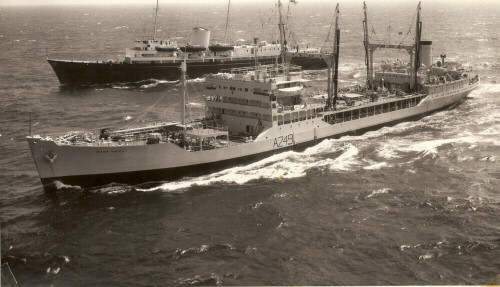
Wave Knight with the Royal Yacht July 1963
The accommodation, like the machinery, was Spartan, just a sink with cold water laid on in each of the officer’s cabins and communal washing and bathing facilities for the crew, although separated by department to port and starboard sides of the after accommodation. In some of the ships these shortcomings were rectified during modernisations and refits during the late 50’s and 60’s when additional turbo cargo pumps were fitted to supplement the existing reciprocating cargo pumps to increase fuel delivery during RAS.
Accommodation was also made available for “DEMS” which was ministry of war transport speak for Defensively Equipped Merchant Ships. After the war when the DEMS gun crews were no longer carried the remaining crew were able to spread out and take advantage of these spaces though the un-insulated decks situated above the machinery spaces gave hot decks which was alright and welcome off Iceland was less than desirable in the tropics.
The engineering spaces, although simple by modern standards, had equipment that was all steam driven giving a somewhat complex arrangement of pipe-work to suit the various services and would have been typical of marine practice from about 1930 onwards.
The diagram below illustrates the typical layout of the Wave boats built in Sunderland by J Thompson, in this case Wave Knight, A249, launched 29th October 1945 as the Empire Naseby and completed in May 1946 and placed under the management of the Athel Line Ltd until 1947 when she became a full RFA. She was scrapped in 1964 after negotiations to sell her to the Indian Navy fell through.

The main power was supplied by two Babcock and Wilcox sinuous header water tube boilers with four oil sprayers in each furnace and the boilers were arranged facing forward into the engine room.

The exception to this was, I think, was either the Teesside or Belfast built ships had the two boilers facing inwards to lessen the effect of the ship rolling on the boiler drum water levels as it was thought that pitching was a lesser evil than the water surge caused by rolling.
The boiler pressure was about 400psi. The boilers were arranged over the main gear box on an elevated platform connected by ladder over the gearbox to the manoeuvring valve level.
The two turbines totalled 5500shp and were constructed either by the builder or, in the case of Wave Knight, the North Eastern Marine Engineering Co. The HP turbine was of the pure reaction type which required that the turbine shaft be manually moved axially in its bearings from the manoeuvring position (to give maximum blade tip clearance) and to be changed to minimum blade tip clearance in the “full away” position. My Chief Engineer took his responsibilities very seriously and was usually the only person to vary the tip clearances which varied from 30thou down to 4 thou to give maximum efficiency across the turbine blades when at “full away”. This was the only time I encountered this elderly design feature which was taken to simplify construction as normally an impulse section was fitted to the turbine shaft first and this section would then exhausting into the reaction section after some work had been taken out of the steam. The lack of sophistication in the turbine construction led to a rather high fuel consumption of about 60 tons of FFO per day for 14.5kts.
The control position, situated on the forward engine room bulkhead, was a very simple stand with only the ahead and astern main throttle valve wheels mounted horizontally and with the astern double shut off valve mounted above and a few gauges for boiler pressure, feed-pump pressure, gland steam pressure and main engine vacuum as well as the telegraph and rev counter. On the deck below were the two Weirs turbo feed pumps.
The main condenser situated under the LP turbine was circulated by a twin cylinder steam driven centrifugal pump of a type originally manufactured by G. Gwynn and Co. Above and to the port of the LP turbine was the generator flat housing two twin cylinder dynamos of 250kw DC output at 110 volts manufactured by the Sunderland Forge Co. On the opposite side was a workshop and very small store with a four cylinder Foden dynamo of 200kw DC output which could be run in parallel with the other two dynamos.
The standard oil lubrication system of the time (and for many years after on steamships) was to pump oil up into a high level holding tank until it overflowed down into the system of pipes feeding the bearings. Should the oil pump fail, a valve, (held shut by the oil being pumped into the tank) would open and there would be about five minutes reserve of oil to stop the ship before the bearings ran hot. The oil overflowing down to the bearings passed through an illuminated sight glass on which one kept a good eye as there was no other alarm or signal to indicate an oil pump failure.
Walking between the main boilers a water tight bulkhead was encountered which gave access to the auxiliary boiler room containing two large scotch boilers that generated steam for all the auxiliaries apart from the turbo feed pumps and the turbo cargo pumps. This included all the reciprocating cargo pumps and all the deck winches (26) and the windlass, tank heating requirements and articisation which included heating pipes around all watertight door clips on the upper deck and a modicum of heating in the accommodation.

The diagram shows a typical 2 furnace Scotch Boiler although the Wave Boats had the 3 furnace type
The firemen in the auxiliary boiler room continued their work in splendid isolation from the rest of the world unless someone was despatched to inform them of an impending RAS. It was possible, and became necessary in Wave Knight, to blow steam from the auxiliary boilers into the main condenser to make up good quality feed water using the auxiliary boilers as an expensive evaporator. An evaporator was fitted to make up to 6 tons of water per day but it was reputed to use 10 tons of water doing it and was not used. The auxiliary condenser and air pump were also situated in this area to collect and return the contaminated (with oil) deck steam returns from the winches and tank heating coils through a hot well filtration system before returning it to the feed tanks
Continuing aft through the auxiliary boiler room the steering gear flat was encountered. The flat held the steering gear and the steam driven refrigeration set. The fridge compressor was driven by a single cylinder steam engine and was typical of all the rotating auxiliary machinery (boiler fans and engine room vents etc) and the engine section is illustrated below:-

Because I only ever sailed northwards from England into colder climes the engine was only run for about half an hour per watch. On engineer cadet was usually tasked with running the fridge engine for its half hour or so. In the tropics the engine would run continuously as the insulation on the fridge compartment was to North Atlantic standards.
The steering gear was unusual in that no hydraulics (except telemotor from the wheel house) were involved. A twin cylinder non compound steam engine controlled by a differential valve gear moved by the telemotor system drove, via a worm wheel on the crank shaft, directly onto a toothed quadrant attached to the rudder stock. The only problem was the heating of the worm wheel in heavy weather due to the constant motion and movement of the rudder stock on the worm wheel. In heavy weather a greaser was tasked with applying copious amounts of lubricating oil on the worm wheel with the surplus being collected from a tray underneath and reapplied.
All of the other auxiliaries were of the “Weir Pump” type with a single double acting steam cylinder driving a double acting plunger pump directly connected to it without any rotating parts. The rather clever weir pump valve gear hesitated at the end of each stroke whilst the internal bits of the valve gear realigned themselves, utilising internal steam ports, for the next stroke. These pumps were used on all services, fuel transfer, burner pressure, lube oil pump to overhead tank etc, fire and bilge duty and oily bilge pumps. A typical arrangement is shown below:-

As an Engineer Cadet I was expected to work at least 5 days per week and on Saturday run the Saturday Morning routines. This consisted of starting and running the following equipment:-
Emergency Ingersol Rand Air Compressor in the for’castle
Emergency Coventry Victor fire pump
Meadows engine in cutter mounted forward
Coventry Victor engine in work boat on main deck
Foden emergency generator in workshop
The Chief Engineer seemed to be the only person able to reliably start the air compressor. The air compressor, fire pump and cutter engines were only started if weather conditions were suitable as they were all sited for’d of the bridge and subject to wave and spray action.
The emergency generator had to be put on line in the dynamo flat switchboard which was all open fronted double bladed knife blades and glowing earth lamps like something out of a Frankenstein movie.
About six of the newer Wave Boats were modernised in the late 50s or early 60s ( Waves Baron, Chief, Ruler, Knight, Prince and ?Laird) which standardised the location of the RAS rigs, one pair just aft of the mid-ship accommodation and one pair just forward of the aft accommodation. A wooden slatted plank deck was built over the tank deck with steel platforms for the winches erected through it. Two steel, 3 foot wide, chequer plate clear ways connected forward and aft on each side about 12 feet inboard. As the officers dining room was mid-ships, all hot food had to be carried this way from the galley aft, quite a challenge in rough weather for the catering staff with waves coming up through the slatted deck.
Additional accommodation was added to the rear of the mid-ship accommodation on the modernised ships and was for an extra four engineers (Jnr 3rd, jnr 4th, 2 extra juniors) and a hospital was added in the centre aft at RAS deck level and on the boat deck level extra deck officer accommodation was fitted for a first officer, doctor (not always carried), two additional radio officers and deck cadets.
This was deemed the minimum additional officer strength required to man a front line RAS tanker as against a freighter in a sustainable way.
The original Wave Boats only had two large reciprocating cargo pumps in the bottom of the aft pump room and each was only capable of pumping about 150 tons per hour which was sufficient for a freighting tanker discharging ashore but this was much too slow to RAS an Aircraft Carrier on the port side and various Destroyer/Frigates on the starboard side so steam turbo cargo pumps were installed. These were fitted some 10 feet above the existing recip. pumps which caused problems of suction loss so normally the recip. pumps kept no 6 centre tank full for the turbo pumps to suck from. A special telegraph was fitted from the top of the pump room to signal “start pumping”,” up 10 psi”,” down 10 psi”,” stop pumping”,” finished with pumps” etc
An oddity of the Wave boats was the installation of a working alleyway 12 feet inboard and 6 feet wide right through the engineer’s accommodation at RAS deck level so hoses for stern refuelling could pass through. The hose was connected by wire to the windlass to control the movement as it payed out. The engineer accommodation on the starboard side was pushed out to the ships side whilst that on the port side was located inboard by 12 feet leaving a promenade deck at RAS deck level under the boat deck on that side.
The additional accommodation installed provided a sheltered spot outside the hospital. Life lines were rigged about 8 feet up over the clearways along the RAS deck. “D” shackles were fitted on the life lines with about 2 feet of rope fixed to the shackle for use of persons passing along the clearway.
Gambling on how far it was possible to throw a shackle down the lifeline usually in port against starboard teams required a precise knowledge of the pitch and roll of the ship with (I’m sure ) the surreptitious addition of some WD40 on one track and thick cable grease added on the other by persons unknown.
I think the galley had been converted from coal (bunker over galley) to oil fired ranges. The day work greaser was required to manually pump up diesel fuel from the pump room to the tank on the roof of the galley until the return tell-tail pipe ran into a pig’s ear next to the pump. This would take at least half an hour of strenuous pumping.
The only air conditioned space was the officer’s saloon and consisted of a cooling unit about the size of an upright piano manufactured by the “Norris Warming Cabinet Co. – Cooling Unit” whose cast brass plate was fixed to the side of the unit. A bath was fitted in the hospital with unusual inward curved rims at the top to prevent water splashing out.