

As mentioned in my remembrances as a junior engineer on the Tidereach all of the old Tide boats (Reach, Flow, Surge and Austral) where designed by a committee incorporating all the experience learned from the second world war. This in particular led to unusually complex ships with a steam version and an electric version of just about every pumping system on the ship except the main turbo feed pumps and the main turbo cargo pumps. The layout was determined by the technology then available and the limitations in metallurgy for control valves etc.

Basically the ship was driven by two steam turbines, one high pressure and one low pressure geared together, giving a total of 15,000 shaft horse power to the single screw. To provide sufficient steam to drive these turbines at full power and sufficient extra for the turbo generators, cargo pumps, tank heating, winches etc. about 50% boiler power was added resulting in the fitting of three Babcock and Wilcox sinuous header boilers with an inter-deck superheater. They each had six burners and separate forced draft fans. This would be about double the boiler output of a commercial tanker of equal size as they would not be expected to steam at 17 knots and pump cargo at the same time.
The three boilers and an auxiliary “Scotch” boiler took up a lot of space and could only be fitted in ahead of the engine room leaving an ever tapering space for the engine room components. Boiler design advanced in leaps and bounds in the early 1960’s (Foster Wheeler ESD1,2,3 and Babcock and Wilcox – Selectable Superheat M10) resulting in the two newer Tides needing only two B & W M10 boilers for the same output as the three boilers in the old Tides and no need for a scotch boiler.
The old Tides also suffered from the fact that the electricity generated was at 220volt, direct current and therefore every electric motor had a very complicated starting system and moreover all motors (and Generators) had maintenance intensive carbon brushes and commutators that required full time regular maintenance and attention from the electricians. This was not an unusual circumstance at sea in the 1950’s until brushless AC alternators and motors became readily available in the early 1960’s when AC systems became more popular and simpler to maintain (1962 Tidespring and Tidepool for example)
A slight aside – the use of DC electrical current meant that everyone had to buy a “vibrator” unit to convert the DC to AC to drive any electrical equipment in their cabins such as radios or tape recorders. It was about as big as two house bricks and gave a variable quality AC output which was not usually noticeable until the tapes were played on the same machine when on leave with a stable grid power supply. They could be bought in Aden from the bum boats but have likely disappeared as a necessity as most ships will be AC now (although at 60 cycles as against 50 in the UK)
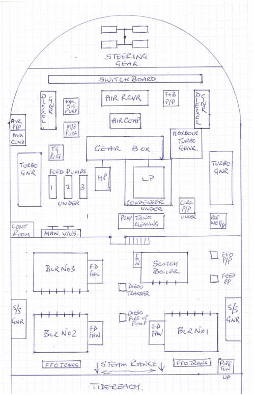
Commencing our tour at the manoeuvring valves at the forward end of the engine room the following photograph illustrates the location.

The main throttle wheels are very evident and the gauges for steam pressure, bearing oil pressure and temperature, gland steam control and pressure (to oppose air leakage into the LP turbine when working under a vacuum) and feed pump pressure can be seen. The telegraph is attached to the vent trunking on the right of the picture with the handle hanging down across the bottom right hand gauge. On the left can be seen the three “igema” remote water level indicators showing the water levels in the three main boilers in the adjacent boiler room.
Close co-operation was necessary when manoeuvring to co-ordinate feed pump output, boiler water level and throttle opening with the demands of the telegraph. A sudden ring of “Stop” required instant action and a second telegraph was used to inform the boiler room where the firemen and fourth engineer would withdraw all but one sprayer from each of the boilers and slow the fans. This would cause a plunge in water level as the steam bubbles collapsed (ebullition) and the feed pumps would have to run up to full speed to compensate and restore the level of water. Conversely, a sharp demand for full speed would cause the boiler steam pressure to drop and the water level apparently rise as steam bubbles were formed in the water due to the water boiling at the slightly lower pressure until the additional burners lit up restored the balance.
To the left of the picture and almost on the centreline of the ship was a watertight door giving access to the boiler-room. Descending the 6 step ladder one arrived on the boiler room deck level immediately behind the “Scotch” boiler. This boiler provided all the steam for auxiliary use such as reciprocating pumps, deck winches, harbour turbo generator, FFO heating and pumping in the engine and boiler room for the main boiler sprayers etc. etc. To the port side of the scotch boiler were its own” Weir” feed pump and oil pump. FFO heaters and pumps for the main boilers we along the bulkhead.

The above photo shows the central firing area with the fourth (sitting in white hat) having a sit down on the left whilst the two firemen watch levels and pressures. H & S would have a fit as no formal protective clothing was issued or even worn. The use of DC electricity precluded the use of strip lighting and normal GLS 150 watt lamps in big lamp shades was the norm giving a rather forbidding illumination to the scene.
On the next level up in the boiler room were the steam to steam generators (SSG). These were pressure vessels supplied with de-superheated steam in an internal coil which then boiled up water for use in the auxiliary systems in place of the scotch boiler when the main boilers were running. The scotch boiler could then be isolated from the steam range. The SSG’s could not use full superheated steam as the control valves would suffer from “wire drawing” or cutting of the control valve surface due to the temperature and pressure of the superheated steam (before hard stellite surfaces on control valves). A large vessel stood in the starboard aft corner of the boiler room which was the de-superheater. Superheated steam was admitted to the top of the unit and feed water for the main boilers was admitted at the bottom, the feed water being heated and the steam temperature lowered to enable it to be used in the turbo feed pumps, turbo generators, SSG’s, and turbo cargo pumps all of which required the pressure, but not the full temperature, of the superheated steam.
There were three major steam systems in the boiler room, “auxiliary” from the scotch boiler and/or SSG at 150 psi., de-superheated steam from the de-superheater for the turbo pumps and generators at 450 psi, 400 degrees F, and the main engine steam at 450 psi 550 degrees F. All of these systems and a few more were arranged along the forward end of the boiler room in “steam ranges” where all the isolation and cross over valves were located. The following photo shows some of the complexity.

Part of the steam range at the forward bulkhead of the boiler room
In the middle of the boiler room were two small motor driven diesel oil pumps, one for topping up all the header tanks (generators, air start compressor, emergency generator, galley ranges) It was run every day until the return pipe from the tanks indicated a good flow indicating all the tanks were full.
The other pump was a lighting up pump for the main boilers and one burner in each boiler was piped to this pump allowing a flame to be established and pressure raised in the boiler from cold as the diesel oil would burn from cold but FFO has to be heated first if there was no auxiliary steam.
Forward of No 1 and 2 boiler was located the two FFO transfer pumps, horizontal two cylinder direct acting Worthington Simpson pumps for topping up the settling tanks for use in the boilers. Each settling tank held about 50 tons of FFO and lasted about 12 hours before changing over to the next tank having first checked for the presence of water by using a test cock at the bottom of the tank and/or water finding paste on the dip stick down the sounding pipe. Having changed to the full tank the empty tank was then pumped up and left for about 12 hours or so for any water to settle to the bottom. Water in the fuel was a serious problem with riveted ships and dubious fuel supplies.

Back in the engine room the above photograph gives the view across the two main turbines ( HP on right, LP on left) looking forward toward the manoeuvring platform seen in the right back ground
Underneath the manoeuvring platform were situated the three Weir’s turbo feed pumps, close enough for the junior to be able to scuttle down the ladder and open or close the feed pump bypass
when greater or lesser demands were made on the pumps as main engine speed changed. The heat from the pumps rose up to the manoeuvring platform situated above the pumps through the open mesh deck adding to the general discomfort to the engineers on the throttles. A slightly older version of the feed pump is illustrated below.

A typical weir turbo feed pump with oil bearings and over speed trip. A discharge bypass valve was fitted between the pump discharge pipe and the suction pipe. This bypass valve remained open until about 65 main engine shaft revs/min when it was closed as the demand for water increased dramatically above this speed.
Packed in along each side was a growling turbo generator, one of which is shown in the next picture. These were about 10 feet from the manoeuvring position.

Aft of the port side turbo generator was located the “Harbour” turbo generator which was a strange machine that took steam at 150 psi from the auxiliary system supposedly for use in harbour, the only problem being the steam requirement was just about the output from the scotch boiler!!!! Because the steam in this unit condensed so readily (being only 150psi to start with), a special “Sharples” oil purifier was incorporated in the lube oil system, strangely located on the opposite side of the engine room, to remove the condensed water which had turned the special lube oil into a white emulsion.
A normal DeLaval purifier for the main engine system was also located nearby along with a “streamline” filter which not only filtered the ME oil through filter packs on a bypass circuit of about 100 GPH but also because it ran under a vacuum was able to distil any water out of the oil.
Aft of the harbour TG were located the two 8 cylinder “National” diesel generators with a third identical unit being located high in the accommodation being designated the “emergency” diesel. This tended to be only run on Saturday mornings as the noise and vibration upset the locals living next door.
Aft of the diesel generators was the main switchboard set at a slightly higher level. Although the main trips were sophisticated and enclosed, a lot of the machine isolation was by open double knife switches.
The photo below gives the atmosphere with the volt meters and ammeters glowing with the main air receiver just in front with the back of the main air compressor motor in front of that.

Below the main level in the engine room all the remaining pumps and auxiliaries were wedged in. There was no large store so engine spares were hung on brackets welded to the ships side between the frames. Bearings, gaskets, pipes were all on display all with the potential of damage or theft.
Space had to be found for fire and bilge pumps, general service pumps, electric and steam bilge pumps, pre wetting pumps (an afterthought), butterworth heater and pumps for tank cleaning, fridge and air con circulating pumps, Main circ pumps, evaporator circ and extract, auxiliary condenser (for steam returns from the deck) and air pump.
The following photograph shows the prop shaft and the lack of space round it.

The shaft space and stern gland and additional equipment added as time went on
Spot the engineer, No MCR or quiet cool working conditions on old Tide Boats, you were right in it

One could not fault the quality of the equipment fitted but only its location in little cubby holes between the ships frames which made operation and maintenance very difficult especially in the lower levels and pump rooms. Tidereach certainly had problems as listed in my piece on being a Junior Engineer in the “life in the RFA” section. The heat had to be believed. Most of us were new to “Tide” boats and so unused to it. The doctor started issuing salt tablets the second day out off Devonport in April with us all taking up to eight of the old penny sized (wartime stock) non fizzy or flavoured tablets every day and when these ran out we had lime flavoured tablets –hurrah.
I think the fourth engineers suffered the most as the junior engineers where jack the lads and could (and were) everywhere in the engine room, steering flat, funnel, pump room and so had a variety whereas the fourth was stuck in the boiler room totally.
I don’t know if meal reliefs are still necessary in this remote control age, but the persons on the 8 to 12 watch had to go down to the engine and boiler room at 1730 for half an hour whilst the 4 to 8 watch went to their cabins mid-ships to eat their evening meal which had been laid out on their cabin desks. It was hoped that steady steaming would occur during this period so no violent manoeuvres would be required as the relieving watch would be in full uniform, but this was not always the case.
During RASing and other “stand by” times the Senior of the watch would be required to double up at the controls for up to two hours before the commencement of his watch and the Junior and fouth for up to two hours after their watch.

Typical RAS with a carrier, the Ark Royal, could last 6 to 10 hours transferring FFO,Dieso, Mogas, Avcat, Avpin, Water and stores.
The engineering staff of the old tides consisted of the following:-
1 x Chief Engineer
1 x Second Engineer (nominally day-work but always about)
4 x Third Engineers (1 on day-work, rotated occasionally)
3 x Fourth Engineers, Boiler room watch only, no rotation.
6 x Junior Engineers (3 on watch, 3 on day-work, rotated)
3 x Engineer Cadets, nominally day work but usually ran pump rooms for RAS
2 x Electrical Engineers
6 x Greasers (3 on watch in Engine room, three on day-work/RAS)
6 x Firemen (2 on each watch in Boiler Room)
1 x Engine Room Store Keeper (PO)
1 x Donkey Man (in charge of all ratings, PO)
34 persons in total working with an extra 2 Pumpmen and 2 carpenters from the deck dept as required.
During exercises and RAS, the Daywork Juniors and apprentices would go down to the boiler room (at any time of the day or night) and crack open the desuperheater steam supply to the pump rooms. Working with the pump men (who would open the correct oil valves on the cargo tanks) the pumps would be slowly run up to full speed and temperature while the oil was circulated round the various cargo ring mains. The pump rooms always seemed to have poor air circulation as only compressed air driven extract fans were permitted. The compressed air was also needed to blow through the rubber hoses at the completion of the RAS to clear the oil. The air pressure dropped and the air driven extract fans would slow down and the fumes in the pump room became very thick which caused our eyes to water.

Phil Woodward (4EO) sweating gently as he administers boiler compound into No 2 boiler to prevent corrosion, water testing and any corrections necessary were undertaken every day

An attentive 3EO watching the engine room greaser blowing down the evaporator. Telegraph behind his ear, tacho showing zero.

The cage where the engine room greaser looked after the evaporators. Again no formal safety wear!

The junior on the left joined the ship from the Liverpool MN “Pool” and was not on RFA contract. He had not been to sea before and found he could not stand the heat. He was, however, a superb machinist having run his own marine engineering company between Brighton and Shoreham. He was able to overhaul most of the pumps, producing new wear rings and truing impellers once a supply of cast brass and bronze hollow “quills” had been obtained in Singapore.

Paul Golding (JEO), in boiler suit, showing that we were allowed out sometimes. This was a run ashore for a banyan/Barbeque on a Malayan Island near Penang

One of the hard working, “hardman” firemen who joined in Liverpool to miss the seaman’s strike.
Quite a few of the black gang joined RFA’s for the first time in Liverpool so that they would not be caught in the seaman’s strike that was due to be called in May 1965. This was the reason for our speedy departure from not only Liverpool but the UK with the refit not completed.
The red wheel on the left is the auxiliary feed water supply valve to the No 1 main boiler. The main valve being automatically controlled by a float activated valve called a “Robot”. The auxiliary valve was only opened to augment the water flow into the boiler if a crash stop was ordered which would require all but one of the fires withdrawn on each boiler. This would cause the boiler water level to fall dramatically.
The red, white and black handles are the operating levers for the gauge glasses showing the boiler water level. These were situated on the steam drum about 15 feet above the firing level. A brass rivet in the deck signified where to stand in order to view the water level in the gauge glass. The gauge glasses were not simple round glass tubes but hefty steel forgings that held two one inch thick special toughened plate glass “glasses” that took special care to repair. It was usual to lay a spare one ready made up alongside the glasses in use so that they would be warm and less susceptible to
thermal shock when required to be fitted.
The body of the gauge glass was forged steel weighing about 40 to 50 lbs and had two flat glasses with gaskets inserted into the body and the whole thing tightened up in a predetermined way. Some people could make up these glasses with no bother, others would do the same, even under supervision, and when the steam was turned on the glass would shatter. It was thought that the glass touching any cold steel surface was stressed in some way and great care had to be taken to ensure that this did not happen.

Typical “Klinger” boiler gauge glasses.
During the 14 months I was on Tidereach we never shut down completely, in harbour with the main boilers shut down the scotch boiler would be running supplying the steam auxiliaries including the harbour turbo generator but to flash up the main boilers required at least one diesel generator to be available as well.
Boiler water consumption was about 20 tons per day but if a serious steam leak occurred this could double. It was normal to let the consumption reach 30 tons per day before corrective maintenance was required which may involve a single main boiler shut down which was possible due to the number of isolation valves provided or a complete shut down if the steam leak was on a common line to the main engines.
The evaporators were usually fed with steam bled from the exhaust pipe between the HP and LP turbines whilst at sea and steam from the scotch boiler if necessary in harbour although this was frowned upon as being expensive to run and the harbour water could difficult to “shock” off the tubes. This was done by stopping the water feed to the evaporator shell, keeping the steam on the heating coil, blowing down the shell till empty, turning off the steam and then spraying cold water onto the heating coils. The natural contraction of the copper coils with the cold water flaked off the scale deposits which then had to be raked out from a special flap at the bottom of the shell. This was a daily task for each evaporator and usually undertaken by the engine room greaser.